Understanding the geometry, materials, and measurement of indexable inserts — and why metrology is key to perfect machining results.
When a workpiece fails to meet surface or dimensional requirements, the cause often lies in a tiny, replaceable component: the cutting insert. This small tool carries enormous responsibility. Its edge geometry, material, and surface finish determine not only the tool life but also the accuracy of the entire machining process. In this article, we explore what makes cutting inserts so critical — and how advanced measurement ensures their consistent quality.
Turning, milling, or drilling — no matter the process, the goal is the same: a flawless, high-precision surface.
In turning, this quality is defined by the cutting insert. The insert’s geometry determines how the material is removed, how heat builds up, and how long the tool can maintain consistent performance. Even the smallest deviation in the cutting edge can result in chatter, poor surface quality, or accelerated wear.

Unlike solid tools, indexable inserts offer the advantage of replaceable cutting edges. Each insert can be indexed, or rotated, to a new edge when one becomes worn. That flexibility makes them a cornerstone of efficient and cost-effective machining — but it also means every edge must be manufactured and measured with identical precision.
Get your comprehensive whitepaper on cutting tool precision
A cutting insert is a sophisticated micro-geometry designed for maximum strength, wear resistance, and consistent chip formation.
The key factors defining its performance include:
Common materials include carbide, cubic boron nitride (CBN), ceramic, and polycrystalline diamond (PCD). Each has its own strengths — from extreme hardness to high thermal stability — depending on the workpiece material.
Thin coatings such as titanium nitride (TiN) or titanium carbide (TiC) improve heat resistance and reduce wear. These coatings can only perform properly when applied on perfectly prepared surfaces and consistent edge geometries.
The edge radius, clearance angle, and rake angle govern how chips are formed and removed.
Even a few micrometers of difference in the edge rounding can affect friction, heat buildup, and tool life.
The roughness on the chip groove influences chip flow and formation. A smoother surface can improve chip evacuation and prevent material adhesion.
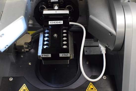
Manufacturers of cutting tools and inserts face one of the toughest measurement challenges in precision engineering.
Critical features like edge rounding, chipping, and surface roughness must be measured in the range of 5–20 µm — often on reflective, coated, and curved surfaces.
Tactile measurement methods quickly reach their limits here:
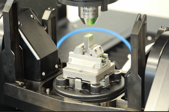
For this reason, optical metrology has become the standard in advanced insert inspection. It allows engineers to measure both form and roughness in full 3D — contact-free and independent of material or coating.
Let’s look at the most decisive parameters for insert performance — and why they’re measured:
Edge rounding radius:
A key factor in coating adhesion and tool wear. Too small, and the edge chips easily; too large, and cutting forces increase.
Chipping and micro-defects:
These determine stability at the cutting zone. Measuring the edge in 3D helps identify even the smallest notches that can shorten tool life.
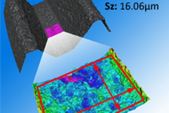
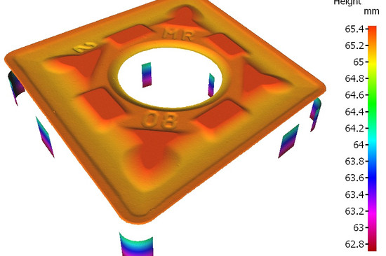
Surface roughness (chip groove):
Affects chip formation, heat transfer, and surface finish on the workpiece. High point density measurements are required to visualize the real texture of the groove.
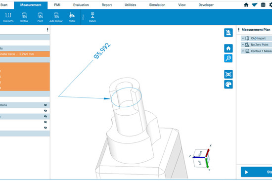
Form and angles:
Features like clearance angle, rake angle, and wedge geometry define how the insert engages with the workpiece. Consistency in these angles ensures uniform performance across all edges in a batch.

Surface roughness of a cutting insert

Surface roughness of a cutting insert - psydocolour
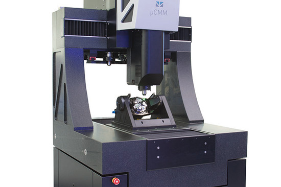
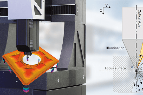
Modern insert production demands fast, reproducible, and traceable measurement results — even under temperature fluctuations, vibration, or ambient light.
Optical systems based on Focus-Variation have proven particularly robust for this task. They capture the full 3D geometry and surface texture of cutting inserts with micrometer precision and are fully automatable for production environments.
This enables manufacturers to verify critical geometries such as:

All about cutting tool precision in one whitepaper
Every perfectly machined workpiece begins with a cutting insert that performs exactly as designed.
By understanding and controlling the geometry of this small yet decisive component, manufacturers secure process stability, tool longevity, and surface quality.
In the end, the cutting insert is far more than a replaceable part — it’s the interface between machine and material, the physical translation of precision engineering into real-world results.
For those who measure cutting inserts daily, precision and repeatability are non-negotiable.
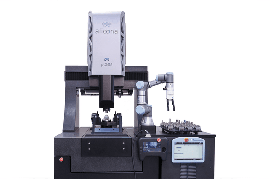
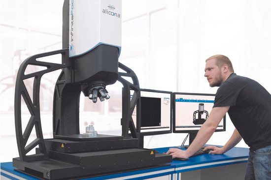
Bruker Alicona’s Focus Variation technology enables users to measure form and roughness in one system, independent of size, material, or coating — from the sharpest edge to the finest chip groove.
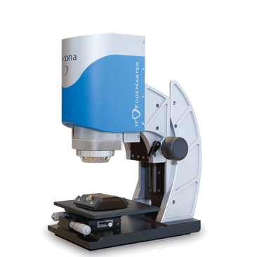
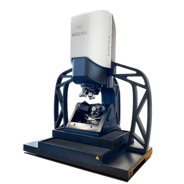
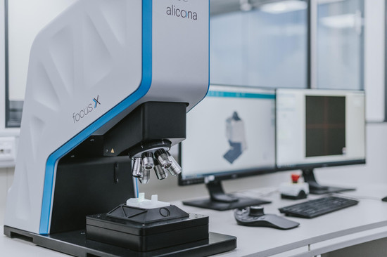
Solutions such as EdgeMaster, FocusX, and InfiniteFocus G6 provide the robustness, automation, and resolution needed to integrate measurement directly into production — making consistent insert quality not just a goal, but a guarantee.
The performance of a turning process can be traced back to one critical detail: the cutting edge. Whether you call it a cutting insert or an indexable insert, its geometry defines tool behavior, wear, and surface quality.
With the right metrology strategy, manufacturers turn this micro-scale precision into macro-scale success — ensuring every edge, in every batch, performs exactly as it should.

-550x366.jpeg)

die_Sonne-550x366.png "Bruker Alicona at AMB 2024 in Stuttgart")


_Nagel-550x366.jpg)

dieSonne-065-868x397-550x366.jpg)
dieSonne-120-550x366.jpg)


dieSonne-137-550x366.jpg)

-550x366.jpg)
dieSonne-(10)-2076x1706-550x366.jpg)

dieSonne-web-(102)-550x366.jpg "Rotation and tilt unit Real3DUnitX")
-550x366.jpg "knee implant measurement")
dieSonne-(23)-1706x1708-550x366.jpg "Key Regions of Turned Parts, Stamped Parts, Round Tools measured")
dieSonne-(01)-2277x1706-550x366.jpg "Production Metrology")

dieSonne-web-(21)-550x366.jpg "Turbine Blade with Cooling Holes")


dieSonne-(9)-550x366.jpg "Alicona Imaging GmbH goes Bruker Austria GmbH")

-1536x1536-550x366.jpeg)


-550x366.jpeg)


dieSonne-268-550x366.jpg)