Blog

Based on the technology of Focus Variation, the optical coordinate measuring system µCMM combines advantages of tactile coordinate measuring technology and non-contact surface measurement. Complex component geometries with the smallest tolerances are easily accessible and can be measured with the highest accuracy using only one sensor. In this article, we answer the top 10 questions about the optical coordinate measuring machine and reveal how it can revolutionize your manufacturing processes. Dive in and find out more!
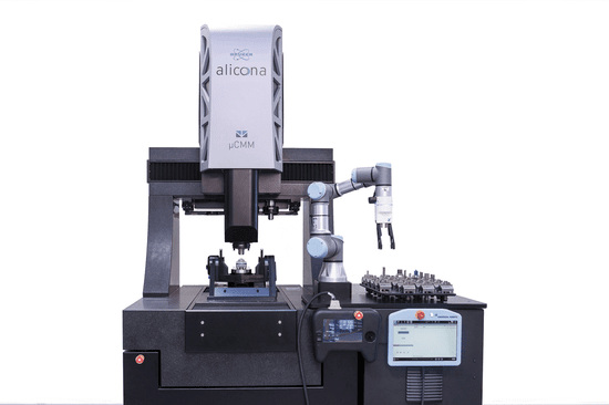
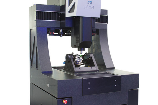
µCMM is the 1st optical coordinate measuring system that enables the measurement of dimension, position, shape and roughness with the highest accuracy using just one sensor. µCMM offers high accuracy over the entire measuring volume 310 x 310 x 310 mm including high measuring point density, which, in addition to dimensional metrology also achieves roughness measurement according to EN ISO 4287/88 (Ra, Rq, Rz...) and EN ISO 25178 (Sa, Sq, Sz...). No other available tactile or multi sensor coordinate measuring system can measure both shape and roughness of components with just one sensor.

Download the technical specifications of µCMM.
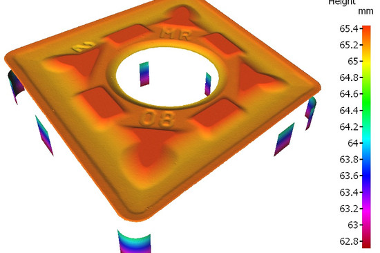
The length measuring deviation remains below E=(0.8+L/600) µm in the entire measuring volume and conforms to ISO 10360. The high measuring point density, even over longer distances, enables the measurement of the smallest component tolerances and the precise determination of the position of these individual measurements in relation to each other. This means that it is no longer necessary to measure the entire component optically. Only those surface details that are relevant need to be measured. This speeds up overall measurement times.

3D measurement of a drill with µCMM. Only relevant areas are measured, it is not necessary to measure the entire part.
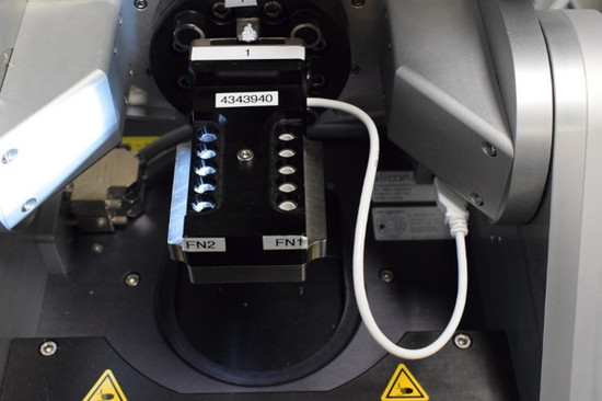
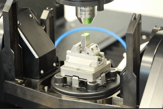
Two calibration standards verify the accuracy of the µCMM coordinate measuring system. The µCMM CalibrationTool, made of Invar steel and calibrated by DAkkS (Germany), is designed to measure and verify larger distances. It shows calibrated sphere distances of (mm) 10, 50, 100, 200, 300, 400. The Advanced µCMM CalibrationTool, calibrated by METAS (Switzerland), is used to verify smaller distances and shape deviations.

Advanced µCMM CalibrationTool for verification of distances and shape deviations.
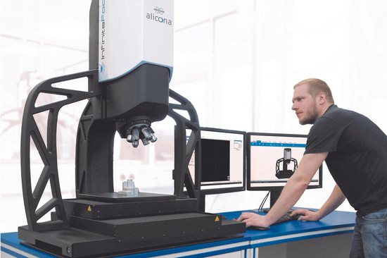
µCMM offers simple, intuitive operation, even for several users, e.g. in a production environment. The control runs i.e. via a specially developed ergonomic controller with multi-touch screen. Depending on the task, only the information necessary for the operator is displayed. When teaching-in a measuring task, this is the measurement field; when changing objective lenses, it is the available lenses. In addition, different speed modes allow either fast rough positioning or focusing on the component detail to be measured.

The ergonomic controller of the µCMM has a touch screen including Live-View.
Yes! The new µCMM operating software MetMaX decides on the basis of intelligent algorithms how to measure in order to obtain an optimal measurement result. This means that users no longer need to overthink their measurement strategy. Once the CAD data set for a component is loaded and aligned, operators can use a simple click to select which GD&T or PMI (Product Manufacturing Information) parameters to measure. MetMaX automatically configures the ideal measurement strategy for an optimized 3D measurement of the part. The software automatically calculates probing directions, tilt, rotation angles, and probing paths in XYZ. Before measurement starts, a virtual simulation ensures a collision-free measurement sequence. The measurement is started by the operator with a click of the mouse and is fully automated. After the 3D measurement is finished, data is automatically analyzed. A reporting system based on Microsoft Word, gives an ok/not ok report.

Measuring systems must not only be able to measure components with the necessary accuracy, but also
record and evaluate data at any time and independently of the knowledge or experience of the operator.
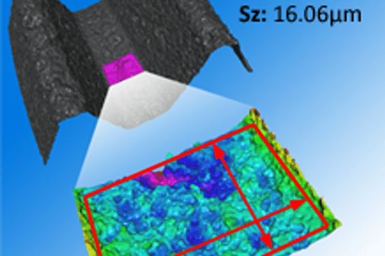
The µCMM is suitable for matt to smooth, highly polished components. By using modulated illumination during the vertical scanning process users not only gain a robust and high-resolution 3D depth data, but also a significantly more robust and higher lateral resolution. This means that surface defects can also be measured on smooth surfaces, i.e. glass, below 0.01µm.

Advanced Focus-Variation technologies enables optimum illumination of each individual
measuring point. This means that even very smooth surfaces can be measured.
The XYZ axes use market-leading scales with a resolution of 3.9 nm. The accuracy of the axes in combination with the solid granite construction and active temperature compensation also enable use in production. In addition, the stability of the measuring system is increased by the air-bearing axes with wear-free drive (linear drive). Additionally, µCMM includes an automatic objective lens changer rack, which has several advantages over conventional coordinate measuring machines. Stationary magazines, as they are usually used in tactile CMMs or multi-sensor measuring systems, reduce the usable measuring volume. With the µCMM optical coordinate measuring system, the usable measuring volume is identical to the travel volume. Furthermore, µCMM can be extended from 3 to 5 axes by means of an automatic rotation and tilt unit.

µCMM with automatic objective lens changer rack: The sensor automatically selects the correct objective.
An automatic rotation and tilt unit "Advanced Real3D Rotation Unit" extends the 3-axes system by a 4th and 5th axis. This opens up automation options for measurements without re-clamping. Also, it increases accessibility to measuring positions on complex components. The rotation unit can be equipped with three jaw, 3R or Erowa clamping systems. With Real3D technology, users measure their components from multiple perspectives, without contact. The different sections measured in 3D are automatically merged into a 3D data set.

Based on the Real3D technology, the µCMM 3-axes system turns into a 5-axes system.
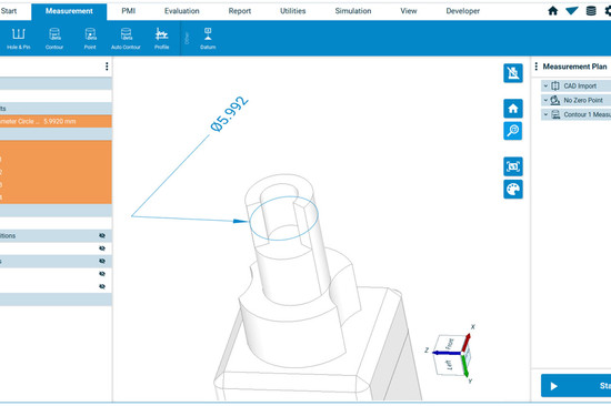
Yes, in combination with the operator software MetMaX µCMM enables the complete automatic measurement and evaluation of components. In just a few steps, users can load the CAD data, align it and select the desired GD&T and PMI features. The software takes care of the rest: it automatically calculates the optimum measurement strategy and travel paths, ensures a smooth measurement process using virtual simulation and starts the measurement at the push of a button. After completion, the data is automatically evaluated, even with adjustments for shape deviations if required. A clear reporting system provides you with immediate feedback on the quality of the measurement results.

The MetMaX software offers a virtual environment in which to test the measurement plan using a digital twin of the optical CMM.
Yes, thanks to µCMM it is for the first time possible to measure holes optically. This is based on the technology Vertical Focus Probing, an extension of Focus Variation. Vertical Focus Probing is based on the use of a partial light cone. In addition to coaxial light, light from different directions is used. This results in individual light beams diffusely reflected from vertical surfaces being captured again by the lens, making flanks of more than 90° highly resolving, traceable and repeatable measurable. Component features such as holes, bores, reference surfaces, contours, lengths, etc. can thus be measured optically with high accuracy, high resolution and short measuring times.

Left: Reflected light can also be detected through the lens if the slope is steeper than 90°.
Right: Measurement of injection nozzles
_Nagel-550x366.jpg)

-550x366.jpg)
dieSonne-065-868x397-550x366.jpg)
dieSonne-120-550x366.jpg)

dieSonne-137-550x366.jpg)